

QJ Digital Gas Relay
Gas relay is a protective device used in oil-immersed transformers and on-load tap changers. The gas relay is installed on the connecting pipe between the transformer tank cover and the oil tank, and a gas guide pipe can be installed to realize ground exhaust and sampling. When an internal fault in the transformer causes the oil to decompose and generate gas or causes oil surge, the relay contacts will operate to connect the specified control circuit, and promptly issue a signal or automatically cut off the transformer switch, distribution transformer, and transformer body. The digital gas relay converts the change in gas volume into a 4~20mA analog output, and can also be configured with RS485 communication protocol, which meets the needs of national smart grid construction.
Keywords:
Category:
Product Description
Product Introduction
Gas relay is a protective device used in oil-immersed transformers and on-load tap changers. The gas relay is installed on the connecting pipe between the transformer tank cover and the oil tank, and a gas guide pipe can be installed to achieve ground venting and sampling. When an internal fault in the transformer causes the oil to decompose and generate gas or causes oil surge, the relay contacts will operate to connect the specified control circuit, and promptly issue a signal or automatically cut off the transformer switch, distribution transformer, and transformer body. The digital gas relay converts the change in gas volume into a 4~20mA analog output, and can also be configured with RS485 communication protocol, which meets the needs of national smart grid construction.
Model Description
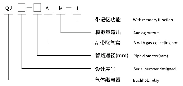
Example 1: QJ10-80AM-J indicates a digital gas relay of the 10th design, with a pipe diameter of 80mm, a gas sampling box, memory function, and analog output.
Example 2: QJ10-80AM indicates a digital gas relay of the 10th design, with a pipe diameter of 80mm, a gas sampling box, and analog output.
Conditions of Use
3.1 Operating Temperature: -45℃~100℃
3.2 Installation Method: The relay pipeline axis should be parallel to the transformer tank cover. The end leading to the oil tank is allowed to be slightly higher, but the inclination of its axis to the horizontal plane should not exceed 4%.
Product Model
| Pipe Diameter (mm) |
Accumulated Gas Volume (mL) |
Oil Speed Setting Range (m/s) |
Factory Setting of Oil Flow Rate (m/s) |
| φ25 | 200-250 | 1.0±0.1 | 1.0±0.1 |
| φ50 | 250-300 | 0.6-1.2 | 0.8±0.1 |
| φ80 | 250-300 | 0.7-1.5 | 1.0±0.1 |
Analog Terminal Wiring Diagram and Contact Capacity
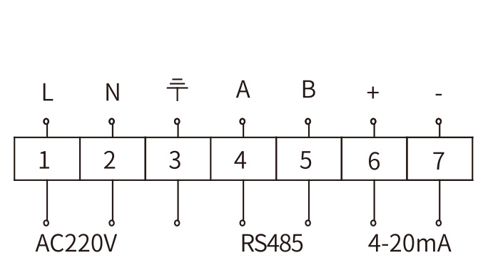
Dual Analog Signals
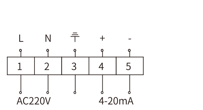
Single Analog Signal
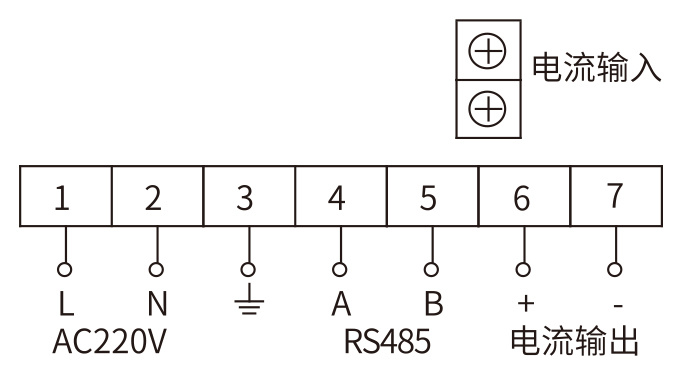
Single Analog Signal
| Current Type | Operating Voltage | Operating Current | Description |
| Direct Current DC | 220V | 0.3A | Time Constant S≤5×10 -3 s |
| Alternating Current AC | Power Factor Cos φ≤0.6 |
Appearance and Installation Dimensions
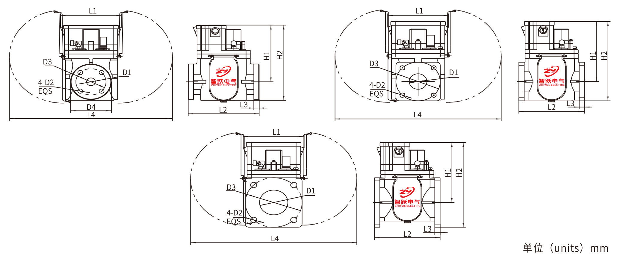
| D1 | D2 | D3 | D4 | H1 | H2 | L1 | L2 | L3 | L4 |
| φ25 | φ14 | φ85 | φ115 | 183.5 | 243.5 | 170 | 200 | 15 | 470 |
| φ50 | φ14 | φ125 | - | 194 | 256.5 | 170 | 185 | 15 | 470 |
| φ80 | φ18 | φ160 | - | 194 | 274 | 170 | 185 | 15 | 470 |
Related Products


Get a quote
Service Hotline
Address: No. 73-16, Puhe Road, Shenbei New District, Shenyang City
Fax: +86-24-23314018
Website: www.syzhiyue.cn
Email: zhiyuedianqi2018@163.com
Scan
Official WeChat