

YSF4II series φ50mm pressure relief valve
The YSF4II series φ50mm pressure relief valve is a newly designed and improved pressure relief valve. This product is used to protect the oil chambers of oil-immersed electrical equipment, such as transformers, high-voltage switches, power capacitors, reactors, and on-load tap changers. The improved pressure relief valve features a more reasonable connection seal for the outlet box, superior three-proof performance, and more convenient locking installation and removal.
Keywords:
Category:
Product Description
Product Introduction
The YSF4II series φ50mm pressure relief valve is a newly designed and improved pressure relief valve. This product is used to protect the oil chamber of oil-immersed electrical equipment, such as transformers, high-voltage switches, power capacitors, reactors, on-load tap changers, etc. The improved pressure relief valve features a more reasonable connection seal for the outlet box, superior three-proof performance, and more convenient locking installation and removal.
Conditions of Use
Installation location: On the tank cover, on a riser, or on the side wall of the upper part of the tank;
Environmental requirements: -30℃~50℃; Working environment requirements: -30℃~+115℃.
The sealing value is an important parameter for selecting a pressure relief valve for a transformer.
(Note: The sum of the highest normal pressure value that appears when the pressure relief valve is in operation plus 7 kPa should be less than the sealing value of the pressure relief valve).
Model Description
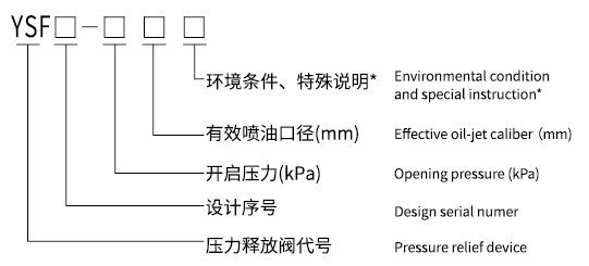
*Note: D- indicates directional oil spraying, K- indicates electrical signal, SK (or KK)- indicates dual electrical signals, J- indicates mechanical signal, TH- indicates for humid and hot regions, TA- indicates for dry and hot regions, T- indicates for dry and humid hot regions, B- indicates with locking device.
Example of marking: YSF4II-85/50KKJBTH indicates a pressure relief valve with a φ50mm spray nozzle diameter, 85kPa opening pressure, dual electrical alarm signals and mechanical alarm signals, for use in humid and hot regions, and with a locking device, based on the second improvement of the 4th design.
Product Appearance and Dimensions

Unit (units) mm
| Product Specifications | D | D1 | D2 | D3 | D4 | H1 | E | F | H | Valve seat mounting bolts Diameter × Quantity |
| 4II-50K | φ74 | φ83.5 | φ94 | φ130 | 125×125 | 28.5 | 102 | φ14 | 140 | M12×4 |
Contact Capacity and Wiring Diagram
| Power Type | Voltage (V) | Current A | |
| Resistive Load | Inductive Load | ||
| AC | 220V | 5 | 3(cos φ=0.4) |
| DC | 0.3 | 0.05(T=7ms) | |
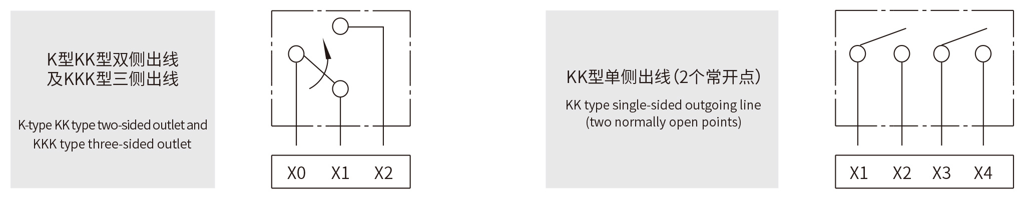
Product Wiring Diagram
Related Products


Get a quote
Service Hotline
Address: No. 73-16, Puhe Road, Shenbei New District, Shenyang City
Fax: +86-24-23314018
Website: www.syzhiyue.cn
Email: zhiyuedianqi2018@163.com
Scan
Official WeChat