

YSF series pressure relief valves with φ25mm and φ50mm diameters
The YSF series φ25mm and φ50mm pressure relief valves are devices used to protect the oil chambers of oil-immersed electrical equipment. They are mainly used in gas-insulated substations, fully sealed transformers, high-voltage switches, power capacitors, reactors, on-load tap changers and other power equipment.
Keywords:
YSF series pressure relief valve
Category:
Product Description
Product Introduction
The YSF series φ25mm and φ50mm pressure relief valves are devices that protect the oil chamber of oil-immersed electrical equipment. They are mainly used in box-type substations, fully sealed transformers, high-voltage switches, power capacitors, reactors, on-load tap changers, and other power equipment.
Conditions of Use
Installation location: On the oil tank cover, on a riser, or on the side wall of the upper part of the oil tank;
Environmental requirements: -30℃~50℃; Operating environment requirements: -30℃~+115℃.
The sealing value is an important parameter for selecting a pressure relief valve for a transformer.
(Note: The sum of the highest normal pressure value that occurs when the pressure relief valve is in operation plus 7 kPa should be less than the sealing value of the pressure relief valve).
Model Description
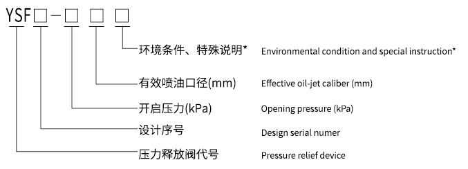
*Note: D- indicates directional oil spraying, K- indicates electrical signal, SK (or KK)- indicates dual electrical signals, J- indicates mechanical signal, TH- indicates for humid and hot regions, TA- indicates for dry and hot regions, T- indicates for dry and humid hot regions, B- indicates with a locking device.
Example of Marking: YSF9-35/50SKJTHB indicates a pressure relief valve with a φ50mm oil spray nozzle diameter, designed in the 9th iteration, with an opening pressure of 35 kPa, dual electrical alarm signals and mechanical alarm signals, suitable for humid and hot regions, and equipped with a locking device.
Product Appearance and Dimensions
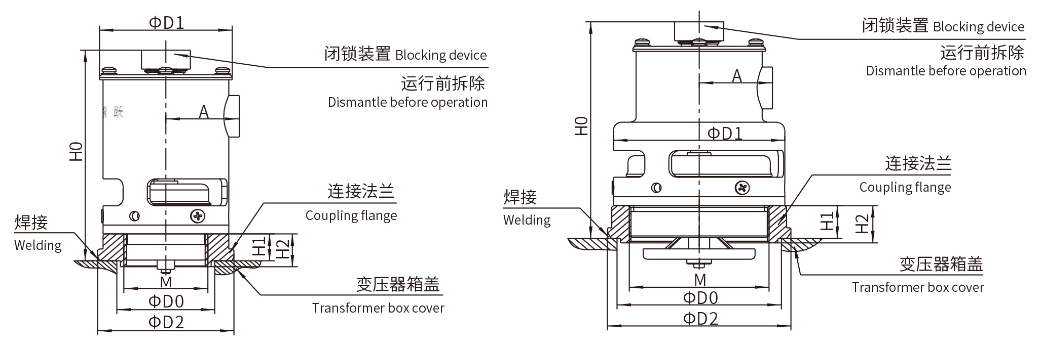
Unit (units) mm
| Model | Oil Spray Nozzle Diameter | D0 | D1 | D2 | H0 | H1 | H2 | A | M |
| Type Nine | φ25 | 56 | 76 | 78 | 144 | 18 | 22 | 42 | M48×3 |
| Type Six | 40 | 76 | 72 | 144 | 18 | 21 | 42 | M38×2 | |
| Type Nine | φ50 | 94 | 98 | 105 | 148 | 22 | 25 | 42 | M80×3 |
Contact Capacity and Wiring Diagram
| Power Type | Voltage (V) | Current A | |
| Resistive Load | Inductive Load | ||
| AC | 220V | 5 | 3(cos φ=0.4) |
| DC | 0.3 | 0.05(T=7ms) | |
Product Wiring Diagram

Related Products


Get a quote
Service Hotline
Address: No. 73-16, Puhe Road, Shenbei New District, Shenyang City
Fax: +86-24-23314018
Website: www.syzhiyue.cn
Email: zhiyuedianqi2018@163.com
Scan
Official WeChat