

QJ 9-80 series double float ball gas relay
The QJ9-80 series gas relay (double float structure) is a protective device used in the on-load tap changer of oil-immersed transformers. The gas relay is installed on the connecting pipe between the transformer tank cover and the oil tank, and a gas guide pipe can be installed to achieve ground venting and sampling. When an internal fault in the transformer causes the oil to decompose and generate gas or causes oil surge, the relay contacts will operate to connect the specified control circuit and promptly issue a signal or automatically cut off the transformer body.
Keywords:
Category:
Product Description
Product Introduction
The QJ9-80 series gas relay (double float structure) is a protective device used in the on-load tap changer of oil-immersed transformers. The gas relay is installed on the connecting pipe between the transformer tank cover and the oil tank, and a gas guide pipe can be installed to achieve ground venting and sampling. When an internal fault in the transformer causes the oil to decompose and generate gas or causes oil surge, the relay contacts will operate to connect the specified control circuit and promptly issue a signal or automatically cut off the transformer body.
Model Description
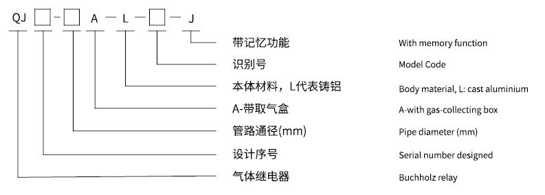
Example 1: QJ9-80A-L-08-J indicates a gas relay with a pipe diameter of 80mm, designed for the 9th time, with a gas sampling box, an aluminum body, and a memory function.
Example 2: QJ9-80A-L-09 indicates a gas relay with a pipe diameter of 80mm, designed for the 9th time, with a gas sampling box, and an aluminum body.
Operating Conditions
Operating Temperature: -45℃~100℃
Installation: The relay pipeline axis should be parallel to the transformer tank cover. The end leading to the oil tank can be slightly higher, but the inclination of its axis to the horizontal plane should not exceed 4%.
Product Model and Wiring Diagram
| Accumulated Gas Volume (mL) | Oil Speed Setting Range (m/s) | Factory Setting of Oil Flow Rate (m/s) | Number of Output Terminals |
| 250-300 | 0.7-1.5 | 1.0±0.1 | 2 |
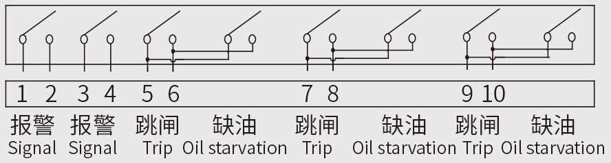
| Identification Code | Contact Description | Wiring Diagram |
| 01 | 1 Alarm 1 Trip (2 Normally Open Single Float) |
 |
| 02 | 1 Alarm 2 Trip (3 Normally Open Single Float) |
 |
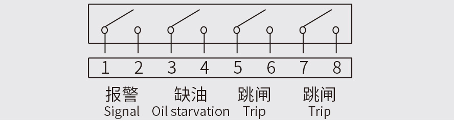
| 03 | 1 Alarm 1 Trip 1 Low Oil (3 Normally Open Double Float) |
 |
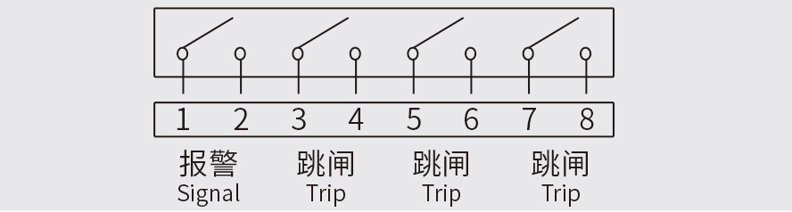
| 04 | 2 Alarm 3 Trip (5 Normally Open Single Float) |
 |
| 05 | 2 Alarm 2 Trip (4 Normally Open Single Float) |
 |
| 06 | 1 Alarm 1 Trip (2 Normally Closed Single Float) |
 |
| 07 | 1 Alarm 1 Trip (2 Normally Open Single Float) |
 |
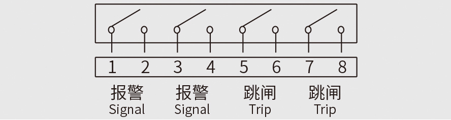
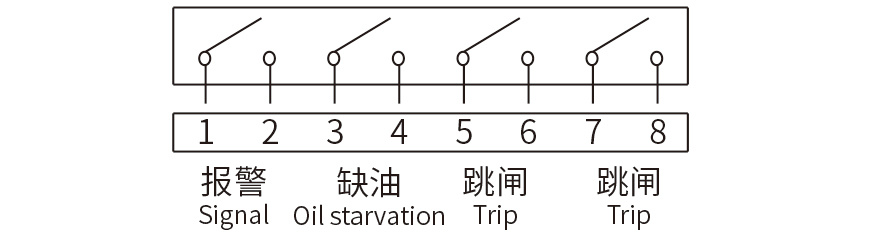
| 08 | 1 Alarm 2 Trip 1 Low Oil (4 Normally Open Double Float) |
 |
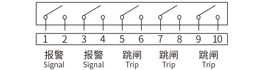
| 09 | 2 Alarm 2 Trip 1 Low Oil (5 Normally Open Double Float) |
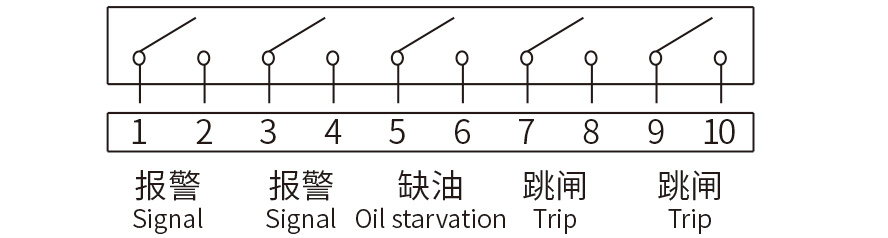 |
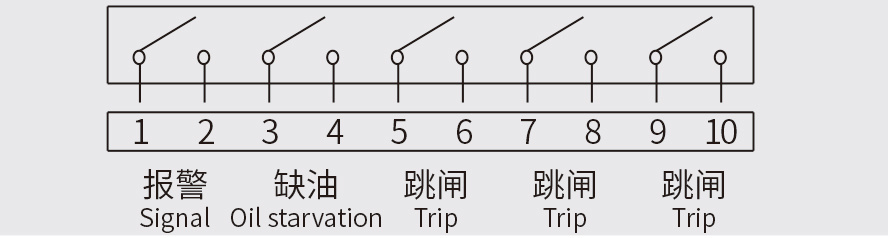
| 10 | 1 Alarm 3 Trip 1 Low Oil (5 Normally Open Double Float) |
 |
| 11 | 2 Alarm 2 Trip 2 Low Oil (4 Normally Open Double Float) |
 |
| 12 | 2 Alarm 2 Trip 1 Low Oil (4 Normally Open Double Float) |
 |
| 13 | 1 Alarm 2 Trip (3 Normally Open Double Float) |
 |
| 18 | 1 Alarm 3 Trip (4 Normally Open Double Float) |
 |
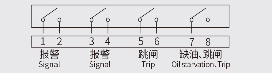
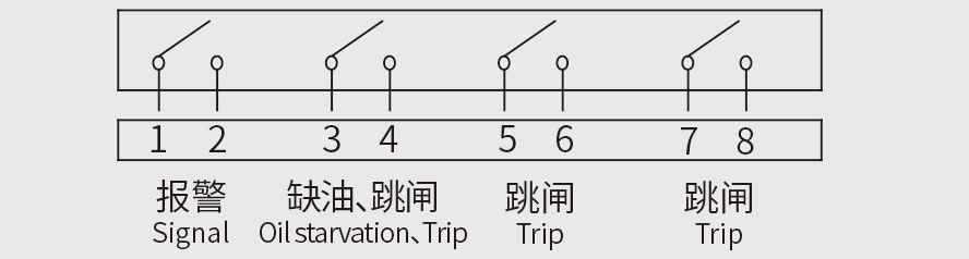
| 20 | 1 Alarm 2 Trip 1 Low Oil (4 Normally Open Double Float) |
 |
| 22 | 1 Alarm 3 Trip 1 Low Oil (4 Normally Open Double Float) |
 |
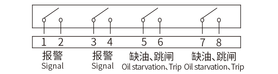
| 23 | 2 Alarm 2 Trip 1 Low Oil (4 Normally Open Double Float) |
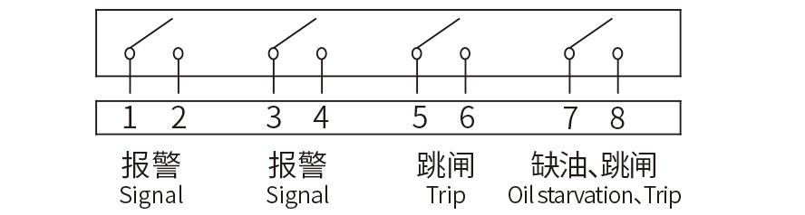 |
| 39 | 2 Alarm 3 Trip 3 Low Oil (5 Normally Open Double Float) |
 |
Contact Capacity
| Power Supply Type | Operating Voltage | Operating Current | Description |
| DC | 220V | 0.3A | Time Constant S≤5×10⁻³S |
| AC | Power Factor Cos φ≤0.6 |
Dimensions and Installation
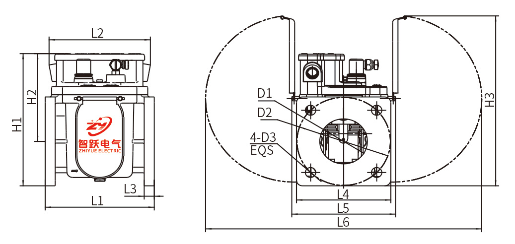
Unit (mm)
| D1 | D2 | D3 | H1 | H2 | H3 | L1 | L2 | L3 | L4 | L5 | L6 |
| φ80 | φ160 | φ18 | 240 | 158 | 306 | 185 | 170 | 15 | 160 | 175 | 470 |
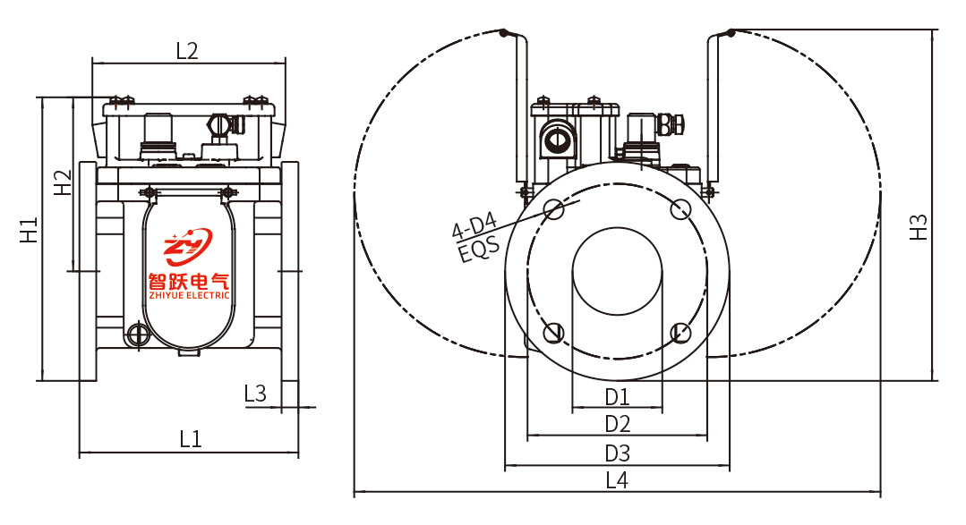
Unit (mm)
| D1 | D2 | D3 | D4 | H1 | H2 | H3 | L1 | L2 | L3 | L4 |
| φ80 | φ160 | φ200 | φ18 | 260 | 159 | 320 | 195 | 170 | 18 | 470 |
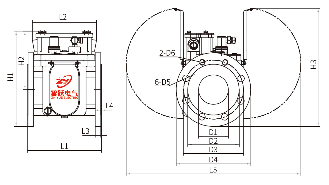
Unit (mm)
| D1 | D2 | D3 | D4 | D5 | D6 | H1 | H2 | H3 | L1 | L2 | L3 | L4 | L5 |
| φ80 | φ138 | φ160 | φ200 | φ18 | m16 | 260 | 160 | 320 | 195 | 170 | 15 | 2 | 470 |
Related Products


Get a quote
Service Hotline
Address: No. 73-16, Puhe Road, Shenbei New District, Shenyang City
Fax: +86-24-23314018
Website: www.syzhiyue.cn
Email: zhiyuedianqi2018@163.com
Scan
Official WeChat