

YSF9 series directional oil pressure relief valves with 80mm and 130mm diameters
Keywords:
Category:
Product Description
Product Introduction
The YSF9 series φ80mm and φ130mm directional oil spray pressure relief valves are mainly used for pressure relief in the oil tanks of large oil-immersed power transformers, power capacitors, reactors, and other equipment when overpressure occurs. When the pressure drops to the closing pressure value of the pressure relief valve, the pressure relief valve reliably closes, ensuring that the oil tank always maintains positive pressure, effectively preventing external air, moisture, and other impurities from entering the oil tank. The pressure relief valve with a directional oil spray device can direct the released transformer oil outward and guide it to the oil collection pool through an oil guide pipe, preventing oil splashing and meeting fire prevention and environmental protection requirements. In addition to the conventional electrical alarm signal, the φ80mm and φ130mm pressure relief valves can also be equipped with an electrical alarm signal function for computer use, which can achieve dual-channel electrical signal output, and each is independently and separately led out. Users can select according to their needs when ordering products.
Conditions of Use
Installation location: On the oil tank cover, on the riser, or on the side wall of the upper part of the oil tank;
Environmental requirements: -30℃~50℃; Working environment requirements: -30℃~+115℃.
The sealing value is an important parameter for the transformer's optional pressure relief valve.
(Note: The sum of the highest normal pressure value that appears when the pressure relief valve is in operation plus 7 kPa should be less than the sealing value of the pressure relief valve).
Model Description
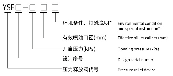
*Note: D- indicates directional oil spray, K- indicates electrical signal, SK (or KK)- indicates dual-channel electrical signal, J- indicates mechanical signal, TH- indicates for humid and hot regions, TA- indicates for dry and hot regions, T- indicates for dry and humid hot regions, B- indicates with interlock device.
Note: YSF8, YSF10, YSF12, YSF14, and YSF16 are all directional oil spray relief valves.
Example of Marking: YSF9-55/130DSKJTHB refers to the 9th design, with a φ130mm oil spray diameter, 55kPa opening pressure, directional oil spray, mechanical and dual-channel electrical alarm signals, for use in humid and hot regions, and with an interlock device.
Product Appearance and Dimensions
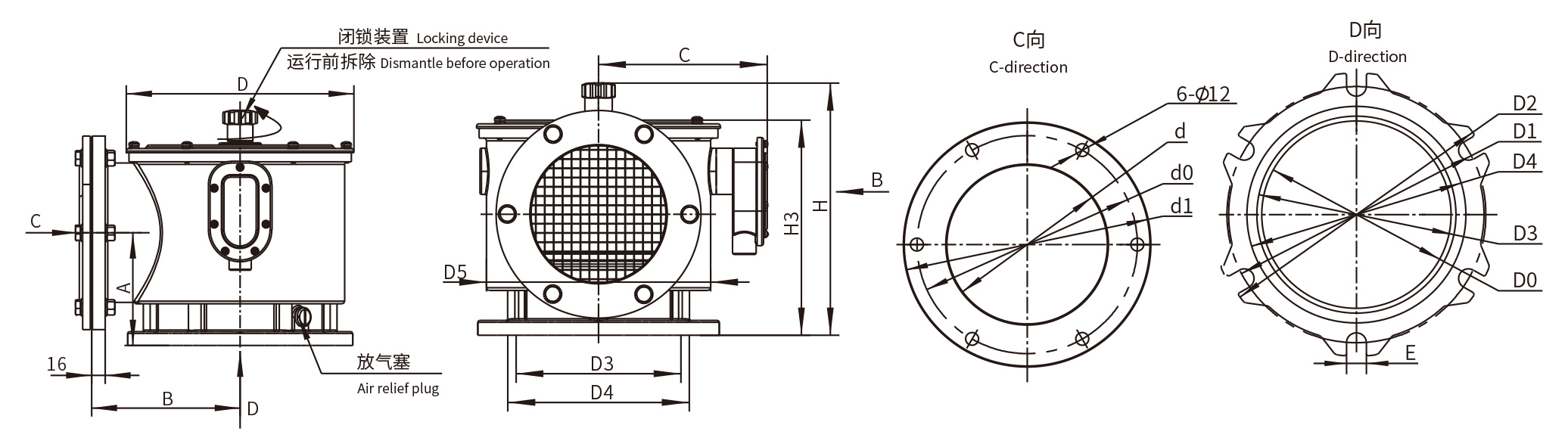
Unit (units) mm
| Model | A | B | C | D | D3 | D4 | D5 | H | H3 |
| YSF9-80D | 113 | 140 | 145 | φ216 | φ138 | φ151 | φ187.5 | 255 | 220 |
| YSF9-130D | 131 | 175 | 185 | φ268 | φ181 | φ199 | φ246 | 275 | 240 |
Unit (units) mm
| Model | D0 | D1 | D2 | d | d0 | d1 | E |
| YSF9-80D | φ122 | φ170 | φ200 | φ100 | φ140 | φ165 | 14 |
| YSF9-130D | φ172 | φ235 | φ260 | φ150 | φ200 | φ225 | 18 |
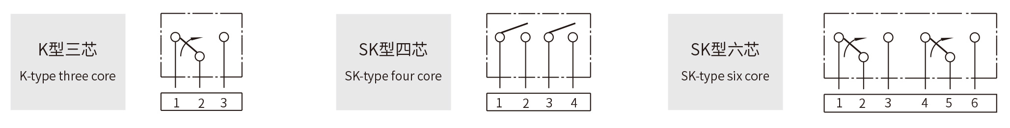
Contact Capacity and Wiring Diagram
| Power Type | Voltage (V) | Current A | |
| Resistive Load | Inductive Load | ||
| AC | 220V | 5 | 3 (cos φ=0.4) |
| DC | 0.3 | 0.05 (T=7ms) | |
Product Wiring Diagram
Related Products


Get a quote
Service Hotline
Address: No. 73-16, Puhe Road, Shenbei New District, Shenyang City
Fax: +86-24-23314018
Website: www.syzhiyue.cn
Email: zhiyuedianqi2018@163.com
Scan
Official WeChat